1986 Ford F250 7.5l Starter Solenoid Wiring Diagram
pmgr starter wiring
How to install a Permanent Magnet Gear Reduction starter on a 1980 - 86 Ford truck.
PMGR stands for Permanent Thousandagnet Gear Reduction, and these starters are smaller and more powerful than the original mode starters that came on these trucks. But, there's another feature that sets them apart from the standard starters - they have a relay congenital-in. And, if the truck is wired to take advantage of that, the current flow through the fender-mounted relay is dramatically reduced.
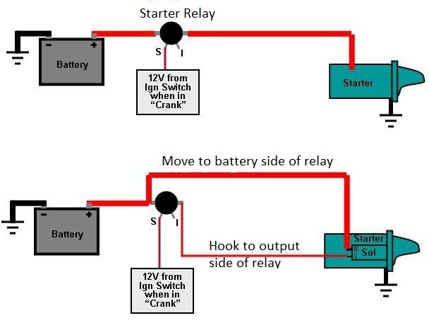
Equally the 1980 - 86 Ford trucks were originally wired, the relay (aka solenoid) gets 12v in on the Ignition Switch wire in the diagram below
(borrowed from this page on FSB), and the relay then bridges the Battery Cablevision to the Starter Cable terminals, spinning the starter. But, since a PMGR starter has its ain relay we can motility the Starter Cable to the bombardment side, every bit shown in the lesser diagram, and run a smaller wire from the output of the relay/solenoid to the small terminal on the starter. Or, you could run the starter cable direct to the battery, in which case the positive battery cable to the relay/solenoid could be made smaller since it won't be carrying the starter'southward load any longer, just the load of the remainder of the truck. Either way, making these changes will ensure that the fender-mounted relay only has to provide enough current to pull the PMGR starter's relay in, thereby dramatically reducing the load on the fender-mounted relay.
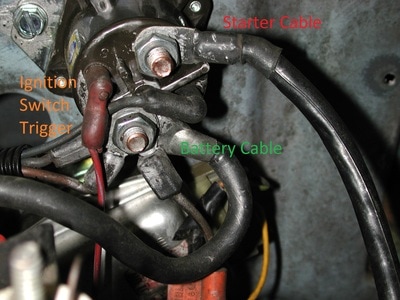
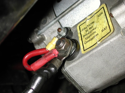
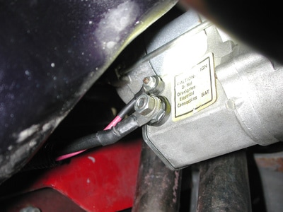
So, allow's see how that would look in reality. My truck chosen Big Blue has had a PMGR starter installed, but whomever installed it did not take advantage of the starter's internal relay. Equally shown in the picture on the left, below, the fender-mounted starter relay has the battery cable on one side and the starter cablevision on the other. So, when ability comes in on the Ignition Switch wire the relay bridges the Battery Cablevision to the Starter Cable terminals, sending power to the starter. In the picture on the correct, the other end of the Starter Cable connects to the big terminal on the PMGR starter. Simply, in guild to pull in the internal relay within the starter there'south a jumper from the large last to the small concluding, and then when power comes down from the fender-mounted relay the relay within the starter is pulled in and connects the Starter Cablevision'southward power to the starter. In other words, both the fender-mounted relay and the PMGR starter's relay accept to acquit the total current of the starter.
But, with a bit of wiring nosotros can use the fender-mounted relay to only pull in the starter's relay, thereby significantly reducing the load on the original relay. In the picture on the left, below, the Starter Cable has been moved to the same stud equally the Battery Cable, meaning that it is at present always hot. Then a #x wire, called the Starter Trigger Wire in the picture, is run from the output last on the fender-relay downwards to the starter's relay last, every bit shown in the picture on the right. Now the fender-mounted relay only carries the current required to pull in the starter's relay, so information technology should terminal forever.
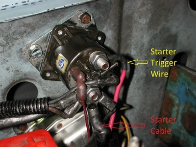
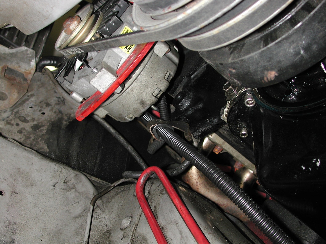
And, the new wire is run in convolute with the original Starter Cable to protect it. In my case the original convolute was besides small to accept both wires, and so I used a larger convolute and ran information technology through the grommet and stand-off the cable originally went through to ensure information technology doesn't come up to grief. After all, that starter cablevision is now hot at all times.
1986 Ford F250 7.5l Starter Solenoid Wiring Diagram
Source: https://www.garysgaragemahal.com/pmgr-starter-wiring.html

Posting Komentar untuk "1986 Ford F250 7.5l Starter Solenoid Wiring Diagram"